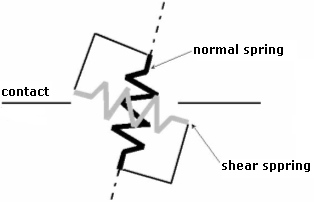
Contact Elements
Two options of the contact element material model are available. One may select either the elastic model with the possibility of plotting contact stresses while assuming the elastic behavior along with the interface or the plastic model. The plastic model is based on the classical Mohr-Coulomb model extended by including the tension cut-off.
This model is therefore well suited when modeling tensile separation. In certain applications such as sheeting structures, this model is vital for receiving meaningful predictions of the soil and structure response.
The basic model parameters are the cohesion c, coefficient of friction μ and angle of dilation ψ. The parameters c and μ can be specified also indirectly by reducing the soil strength parameters c and tan(φ) of adjacent to the contact. If the contact is assumed between two soils (rocks) then the one having smaller values of c and φ is used in the reduction step.
The contact parameters are then defined as:
![]()
![]()
If no better information regarding the reduction of parameters is available one may use the following values. For steel structures in sandy soils, the reduction parameter equal to 2/3 is reasonable while for clays the value of 1/3 can be used. These parameters usually attain higher values when concrete structures are used. In general, the reduction parameters should be less than 1. The dilation angle plays the same role as in the case of standard soil models. Just recall that by setting ψ = 0 we prior assume elastic behavior in the tension/compression. The plastic deformation is thus limited to shear.
Additional parameters of the contact material model are the elastic stiffnesses in the normal and tangential directions kn and ks, respectively. They can be imagined as spring stiffnesses along with a given interface. A reliable selection of the values of these parameters is not an easy task and is usually problem-dependent. To shed a light on this subject one may relate these stiffnesses to the material parameters of the soil adjacent to the contact. The following relations then apply:
![]()
![]()
where: | t | - | assumed (fictitious) thickness of contact (interface) layer |
G | - | shear modulus of elasticity | |
E | - | Young’s modulus of elasticity |
In the case of distinct materials (E1, E2, G1, G2) we take the lower value of ks and kn.
Although in case of a fully plastic behavior the selection of parameters ks and kn is not essential, the values assigned to these parameters are decisive for the success of the solution of a given nonlinear problem. Providing these values are two large (above 100000 kN/m3) the iteration process may oscillate. On the other hand, setting the values of ks and kntoo low (below 10000 kN/m3) lead to nonrealistic deformations of structure.
The default setting in the program is 10000 kN/m3.
 Visualization of elastic stiffnesses